EZWheel, Inc. Protected under U.S. Patent 5,323,867
|
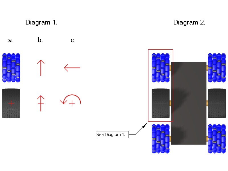
The EZWheel Six Wheel Mobile Platform has a fore and aft EZWheel omniwheel
mounted on each side of the vehicle with a conventional pneumatic tire
between them. The three left side wheels are mechanically linked and
driven by one motor. The right side wheels are also linked and driven
by a second independent motor. This six wheel mobile platform is
steered by controlling the speed and direction of the left and right
side wheels independently. As is the case for a military tank, bull
dozer, or skid steer tractor, the platform will turn in place about
its center by driving the left and right side wheels in opposite
directions (at the same speed).
As we shall show, the EZWheels tend to rotate at the same speed as the center pneumatic wheels even if the EZWheels are not mechanically linked to the center wheels. This is true whether the vehicle is moving straight forward or is in the process of turning. An important consequence of this fact is that the fore and aft EZWheels can be driven via direct linkage with the pneumatic wheels without differential gearing. In addition, the use of transverse wheels, each having a small foot print, reduces scrubbing from forces perpendicular to the direction of motion of the EZWheel. The combination of the EZWheel tending to naturally rotate at the same rate as the pneumatic wheel combined with the use of transverse wheels results in very efficient operation with low energy loss due to friction in directions other than the intended direction of motion of the platform. Consider the following diagram:
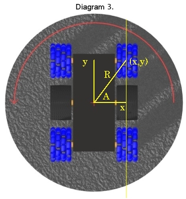
The Diagram 1a is a bird's eye view of an EZWheel in front of a central pneumatic drive wheel. Diagram 2 shows the entire platform but let us concentrate on the relative motion of the central drive wheel and one of the EZWheel omniwheels. An intuitive explanation of the relative rotational speeds of the wheels goes as follows. Think about the pneumatic wheel and the EZWheel directly in front of it. The drive wheel does one of two things. It either moves forward (Diagram 1b) or it rotates about a vertical line drawn through its center (Diagram 1c). When it moves forward, so does the EZWheel in front of it. When the drive wheel turns about the center of a vertical axis through its center, the EZWheel only has motion perpendicular to the forward direction (just the transverse wheels turn). The arrows in the pictures above show these relative motions. All motion of the vehicle can be decomposed into rotations or translations of the drive wheel. Hence, all motion of the EZWheel is either forward at the same rate as the drive wheel or perpendicular to its direction of motion. We can make the situation more precise as follows. Imagine a large surface in the shape of a disk with the origin (0,0) at the center of the disk and an EZWheel resting on the surface of the disk at coordinates (x,y) where y is the forward direction along a line across the disk, x is perpendicular to that line and x > 0 (the line does not go through the center of the disk). We picture this in Diagram 3. Instead of the wheel moving, pretend for the moment that the EZWheel remains fixed at position (x,y) and the disk rotates. The EZWheel will rotate in the y direction at a speed equal to the surface of the disk in the y direction and the little wheels of the EZWheel will rotate in the x direction, each at a speed equal to the surface of the disk in the x direction at their points of contact.
The speed in the y direction only depends on x, not on y. In other words, no matter where you place the EZWheel along a line in the y direction, its forward rotational speed will be the same, depending only on how far it is in the x direction from the center of the disk. That's just another way of saying that wheels that are all lined up one in front of another all rotate at the same speed! A more formal derivation of these properties uses basic trigonometry and calculus, as follows. Let R be the radius from (0,0) to (x,y) of a circle drawn through (x,y) around the origin. Let A be the angle from the x axis to the line through (x,y). Then, from elementary calculus we can derive the following: d(sin A)/dt = K cos A, for some constant K ==> d(y/R)/dt = K (x/R) ==> (1/R)(dy/dt) = K (x/R) ==> dy/dt = K x i.e., the rate of change in the y direction is proportional to x and only depends on x, the distance of the line from the center of the disk.
Strictly speaking, this explanation only applies to a wheel that has
zero thickness, since for a real wheel, the distance x to the inner
part of the wheel is less than the distance x to the outer part of the
wheel. When the physical characteristics of an actual EZPlatform are
added to the equations, there are inevitable small losses in
efficiency, as there is with any real-world vehicle. Nevertheless,
the EZWheel platform is quantifiably more efficient than competing
designs.
|